Nobody sells a cheap IMU with PPS input, so I built one
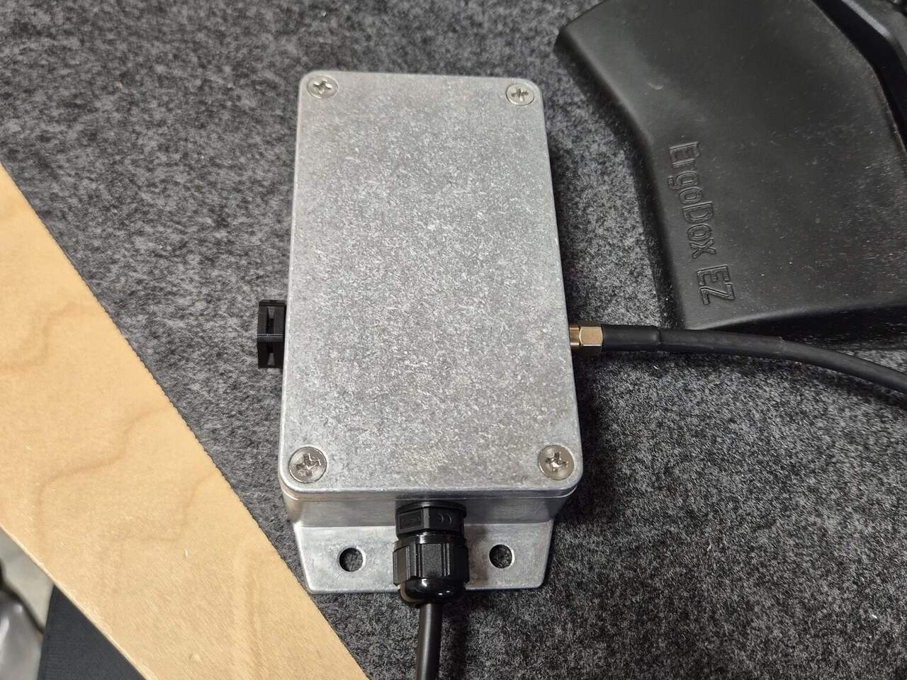
Building custom hardware in the age of LLMs.

The prototype on the bench and its live data in Rerun. Turning the board turns the box.
At Cartio Robotics we needed an IMU (Inertial Measurement Unit) for our data collection platform. The commercially available ones were either not that good, good but expensive, or locked to some proprietary protocol. So I built one.
Just to be clear: I did not build the actual IMU sensor. What I built is everything around it to make it a functional unit: the microcontroller interface, the firmware, the protocol and the enclosure.
It turns out you can get a pretty good IMU with GPS PPS (Pulse Per Second) sync for about 50€ in parts, plus some bits and pieces from your junk box.
Why would you want an IMU?
An IMU measures acceleration and rotation rate along the x, y and z axes, sometimes with a magnetometer thrown in. They range from fibre-optic units on nuclear submarines that cost as much as a car and are good enough to find true north by sensing the Earth’s rotation, to MEMS (Micro-Electro-Mechanical Systems) chips that cost less than a coffee. These are the ones in your phone. The difference between them is mostly how quickly their errors grow.
For lidar and camera odometry and mapping, which is what we do, the IMU earns its keep in three ways.
- Odometry. It gives the Kalman filter a much better prediction between update steps, rather than the motion model “assuming we kept going at the same speed”.
- Point cloud deskewing. A spinning lidar takes tens of milliseconds to complete a sweep. If the vehicle moves during the sweep, the cloud smears. The IMU tells you how much so you can correct for it. This is called deskewing.
- Dead reckoning. When GNSS drops out under trees or between buildings, the IMU keeps you going for a while. Not forever. Drift is the whole game with cheap sensors.
We are also curious about how much performance you can squeeze out of cheap sensors, and about arrays of cheap sensors instead of one very expensive one.
The IMU sensor: TDK ICM-42688-P
I settled on the TDK ICM-42688-P on a widely available breakout board. The most-cited alternative is the Bosch BMI270, which is everywhere in the FPV and flight-controller world. For reference I’ve also put the MPU-6050 in the datasheet comparison at the end of this post. That’s the chip inside most of the cheap “6-axis IMU” modules on AliExpress and in a lot of hobby robots.
I went with the TDK for four reasons:
- Availability. Easy to get, at a good price, on a well laid out breakout board.
- Software support in Rust (the language I prefer for embedded applications).
- Three times better temperature stability on gyro bias, and four times on gyro scale factor. For a sensor that lives in an aluminium box on a vehicle, temperature is the enemy.
- Lower noise. The BMI270 has about two and a half times the gyro noise and twice the accelerometer noise.
The microcontroller: RP2040
The ICM-42688-P talks SPI (Serial Peripheral Interface). SPI is a common chip-to-chip bus for short-distance, synchronous, full-duplex communication. To get USB and/or Ethernet you need a microcontroller to bridge the sensor and the host. I used the RP2040 for its low cost, excellent documentation, excellent debugging support and excellent Rust tool chain support.
The RP2040 is a dual-core Cortex-M0+ with a programmable I/O block
(PIO) that is handy for odd timing jobs like PPS. Rust support has
been solid since the rp2040-hal crate landed in 2021, and Embassy
has had first-class support for it for a couple of years now.
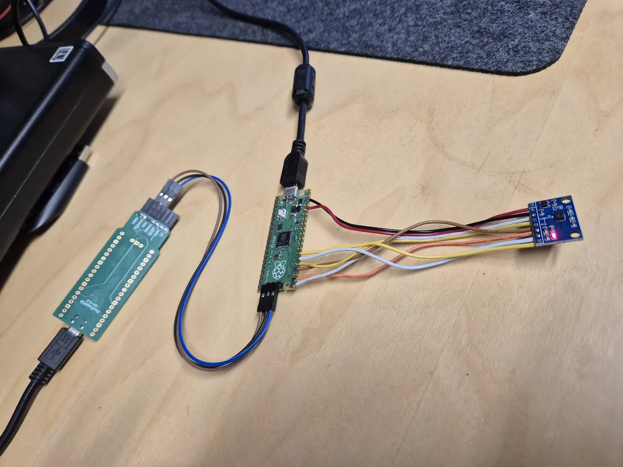
SPI wired up
Writing the firmware: Closing the loop
I have been writing software for a very long time, and I used to write all code my hand. Even assembly. For better or worse, I guess those days are gone now. In this project I used Claude Code for rapid prototyping but any modern agent should work, although results may vary. I have found that using Claude Code works really well for firmware development provided you meet some requirements:
Documentation. Put all available documentation in the project
repository (data sheets, reference manuals, crate docs) and tell
Claude how to search it efficiently. I’m fond of ripgrep-all for
this, since it searches inside PDFs and caches the text.
Let Claude guide the hardware. Claude is very good at pin assignment. Give it the data sheet and the board pin out and let it propose which GPIO does what.
Tooling. I use NixOS. All tools and tool chain requirements live in a direnv in the project repo. This avoids dependency hell. NixOS is also very good at managing the udev rules you need for different hardware.
Close the loop. I have found that for best performance, your agent needs a way to inspect and test its own work. With the IMU soldered in, I connect the target board both via USB and via SWD using a Pico Pi SWD debug probe. Claude can then flash, read logs, halt, reset and poke registers without me in the middle.
The whole firmware is about 1800 lines of Rust (using Embassy-rs ).
Firmware overview
The Pico reads the ICM-42688-P over SPI at 1 kHz, driven by the
sensor’s data-ready interrupt, and streams every sample as a MAVLink
HIGHRES_IMU message over USB. Each message carries the Pico’s own
microsecond timestamp of the data-ready edge, so USB latency does not
matter. A HEARTBEAT and SYSTEM_TIME go out at 1 Hz, TIMESYNC
replies on request, and every PPS edge goes out as a CAMERA_TRIGGER
message. MAVLink has no PPS message, but it does have a camera and IMU
sync-pulse message, which is the same thing wearing a different hat.
By using the MAVLinks protocl we get easy integration with existing software. It also makes agentic coding easier because our implementation can be cross checked against an existing implementation.
One detail for anyone using the mavlink crate in no_std: serialise
each message through its concrete type, not through the MavMessage
enum. The enum pulls every message of the common dialect into flash.
Trick one: timestamps in hardware, not in software
The obvious way to timestamp an edge is an interrupt handler that reads the timer. The problem is that the handler runs when the CPU gets to it. With USB traffic, other interrupts and the odd critical section, “when the CPU gets to it” varies by tens of microseconds, and those show up as jitter in the data.
The RP2040 has programmable I/O (PIO) state machines, tiny processors that run independently of the cores. One state machine per input runs this program:
.wrap_target
    wait 0 pin 0
    wait 1 pin 0
    push noblock
.wrap
This is a rising edge detector:
wait 0 pin 0stalls until the input pin is low. The0afterpinis relative to the state machine’s input base, so it means “the first input pin”, not GPIO 0.wait 1 pin 0stalls until the same pin goes high. Together the two waits mean the program only gets past this point on a low-to-high transition, once per edge.push noblockcopies the state machine’s input shift register into the RX FIFO. Nothing is ever shifted into that register, so the pushed word is always zero. Its value does not matter. Its arrival is the event..wrap_targetand.wraploop back to the top at no instruction cost.
The RX FIFO going from empty to not empty is wired as the pacing request for a DMA channel whose only job is to copy the 1 MHz timer register into a static variable. So the chain is: pin goes high, state machine pushes, DMA fires, timer value lands in RAM. The edge is stamped within a few clock cycles of happening, whatever the CPU is doing at the time. Software only wakes up afterwards, checks the DMA fired, reads the stamp, and re-arms the channel for the next edge.
pub async fn next(&mut self) -> Result<u64, StampError> {
    self.sm.rx().wait_pull().await;          // an edge happened

    let ch = pac::DMA.ch(self.dma);
    let fired = ch.trans_count().read() == 0 && !ch.ctrl_trig().read().busy();
    let stamp = STAMPS[SM].load(Ordering::Relaxed);
    let overrun = !self.sm.rx().empty();     // more than one edge queued?
    self.arm();                              // ready for the next one

    if !fired   { return Err(StampError::NotFired); }
    if overrun  { return Err(StampError::Overrun); }
    let now = Instant::now().as_micros();
    let age = (now as u32).wrapping_sub(stamp);
    if age > MAX_AGE_US { return Err(StampError::Stale); }
    Ok(now - u64::from(age))                 // extend 32-bit stamp to 64
}
The overrun part is to check that the above does’t fail for some reason.
Trick two: run from RAM
The RP2040 executes code from external flash through a 16 KB cache. A cache miss stalls the core for a few hundred nanoseconds. I saw this as timestamp outliers, and as CPU load that changed between builds for no reason other than what happened to land in the cache.
So at boot, before anything else runs, a short assembly routine copies
all code from flash into a 64 KB region of SRAM and the chip runs from
there. The linker script puts every .text input section into a
.ram_text output section whose load address is in flash and whose
run address is in RAM. Only the reset path, the copy loop itself, and
the HardFault handler stay in flash. Embassy already defines the
pre-init hook, so the linker wraps it:
__wrap___pre_init:
    ldr r0, =__sram_text
    ldr r1, =__eram_text
    ldr r2, =__siram_text
0:  cmp r1, r0
    beq 1f
    ldm r2!, {r3}
    stm r0!, {r3}
    b 0b
1:  ldr r0, =__real___pre_init
    bx r0
(The 64kB limit is checked at build time).
Mechanical
An IMU that is not rigidly mounted is a very expensive random number generator. I put it in a die cast aluminium box, drilled the lid for mounting, and fixed the breakout with standoffs. The SMA connector is the PPS input. The cable gland carries USB. The black gland on the opposite side is a pressure vent to prevent condensation inside the box.
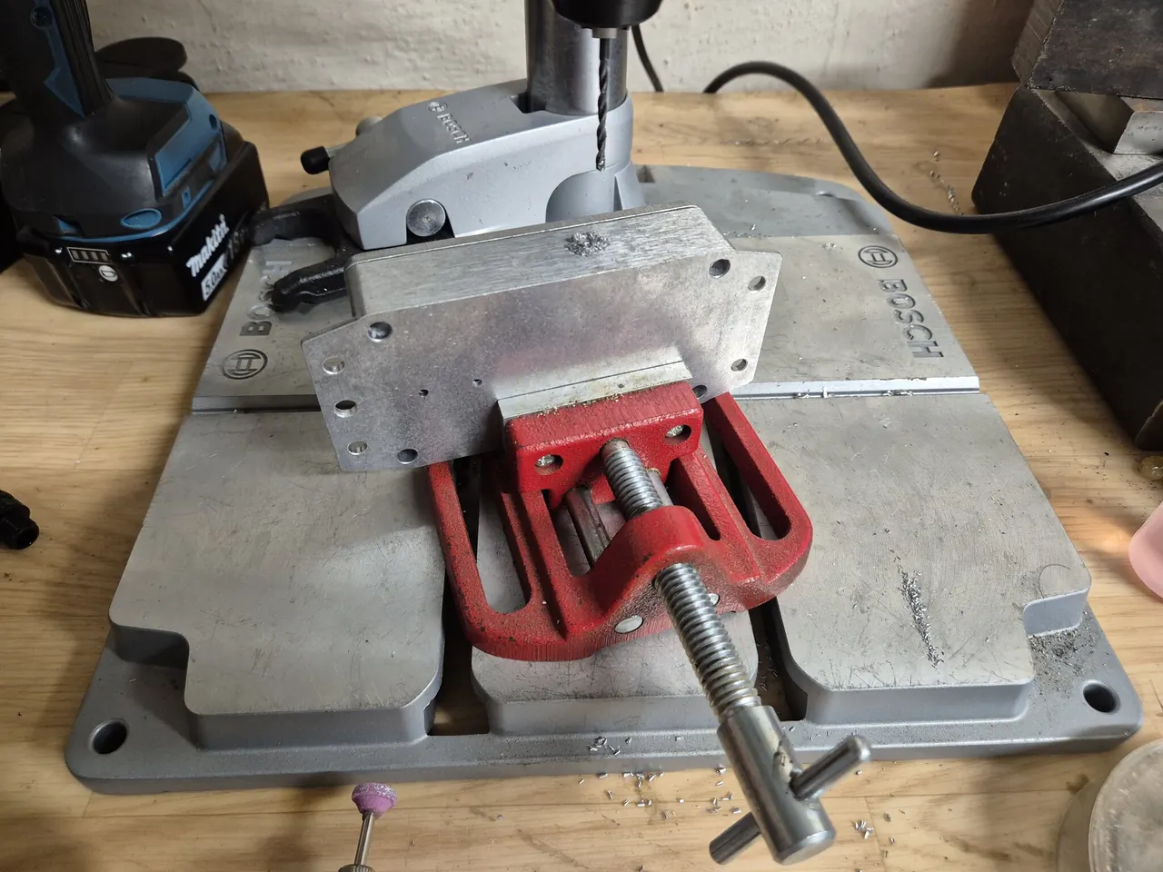
Drilling the enclosure.
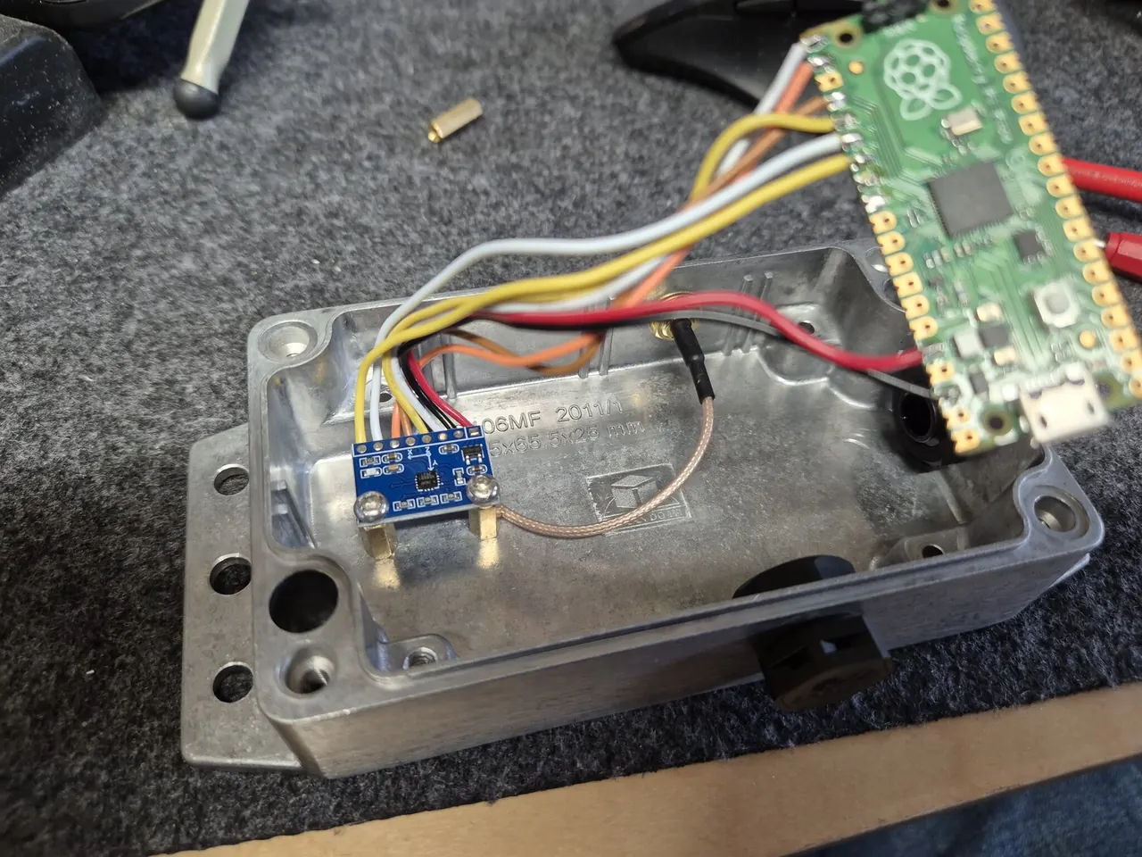
Everything in the box. Breakout on brass standoffs, PPS coax to the SMA.
Conclusion
When I wrote this code, only God and I knew how it works. Now, only God knows it.
For about 50€ in parts I now have the IMU I could not buy: open hardware, open firmware, a standard protocol, and a PPS input so it shares a clock with the GNSS receiver and the lidar.
I am blown away by what a modern LLM can do in firmware and hardware development. The agent came up with tricks I am fairly sure I would not have found myself: timestamps captured in hardware, running from RAM, a HardFault handler that hides its evidence in the watchdog’s scratch registers. If you know how to build hardware, and you set up a debug environment where the agent can flash, probe and test its own work, it will accelerate firmware development enormously. What used to take months now takes days.
The price is intimacy with the code. When you have not written every line yourself, you do not know it the way you used to. The quote at the top of this section used to be a joke about forgetting. Now it’s true from day one. For a prototype I think that is a good trade. For code you have to maintain for years, I am less sure. Or, as SpongeBob would ask: Where is the love?
Datasheet comparison
Typical values from each vendor’s datasheet for the ICM-42688-P, the BMI270 and the MPU-6050, as referenced from the sensor section :
| Parameter | ICM-42688-P | BMI270 | MPU-6050 | What it limits |
|---|---|---|---|---|
| Gyro noise density | 2.8 mdps/√Hz | 7 mdps/√Hz (performance mode) | 5 mdps/√Hz | Short-term heading noise |
| Initial gyro offset | ±0.5 °/s | ±0.5 °/s | ±20 °/s | Must be calibrated out at startup |
| Gyro zero-rate drift vs temp | ±0.005 °/s/°C | ±0.015 °/s/K | ±20 °/s over -40 to 85 °C (≈0.16 °/s/°C) | How long dead reckoning stays useful |
| Gyro sensitivity drift vs temp | ±0.005 %/°C | 0.02 %/K | ±2 % over the range | Heading error proportional to how much you turn |
| Gyro cross-axis sensitivity | ±1.25 % | 0.2 % | ±2 % | Turn leaks into the other axes |
| Accel noise density | 65 to 70 µg/√Hz | 160 µg/√Hz | 400 µg/√Hz | Short-term velocity noise |
| Initial accel offset | ±20 mg | ±20 mg | ±50 mg X/Y, ±80 mg Z | Must be calibrated out |
| Accel zero-g drift vs temp | ±0.15 mg/°C | ±0.25 mg/K | ±35 mg X/Y, ±60 mg Z over 0 to 70 °C (≈0.5 to 0.9 mg/°C) | Position drift over a long run |
| Rust driver | icm426xx |
bmi270 |
mpu6050 |
Links
- MAVLink 2: https://mavlink.io/en/guide/mavlink_2.html
- ICM-42688-P datasheet (PDF): https://product.tdk.com/system/files/dam/doc/product/sensor/mortion-inertial/imu/data_sheet/ds-000347-icm-42688-p-v1.6.pdf
- RP2040: https://www.raspberrypi.com/products/rp2040/specifications/
- Pico Pi SWD probe: https://github.com/raspberrypi/debugprobe
- ripgrep-all: https://github.com/phiresky/ripgrep-all
- Rerun (the visualiser in the video): https://rerun.io
icm426xxcrate: https://docs.rs/icm426xx/latest/icm426xx/